Data Centres & AI Infrastructure
What is the difference between Tier I, II, III and IV data centres?
What Uptime Institute Tiers I to IV describe, what they do not guarantee and how to verify a design or provider's claim.
Data Centres & AI Infrastructure
Match redundancy to the consequence of failure, then check the paths and the equipment's own power design.
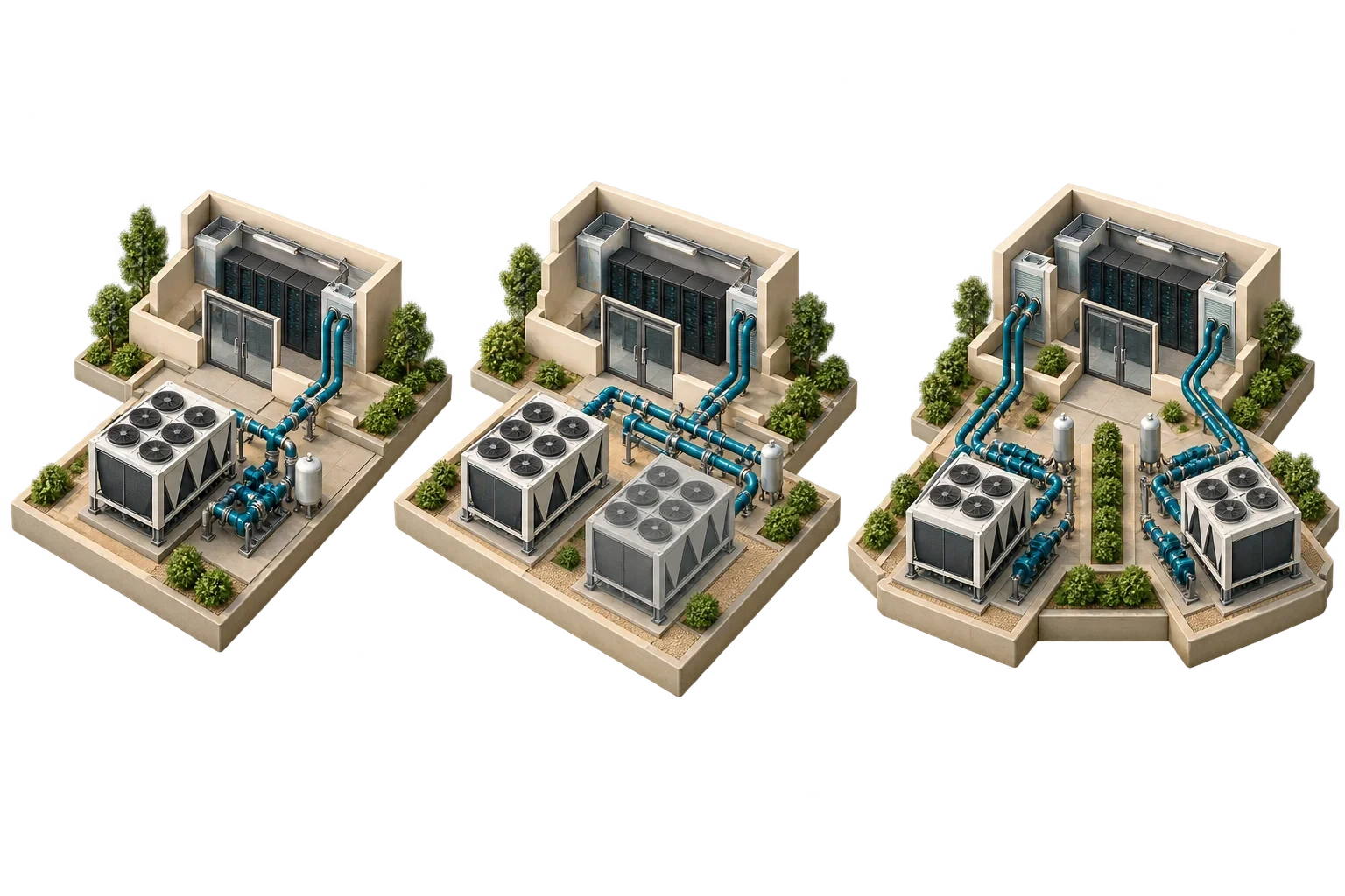
The notation describes how much spare capacity a system has relative to what its load needs. N is exactly the capacity required to carry the load, with nothing spare. N+1 adds one extra unit, so that any single unit can fail or be maintained while the others carry the load. 2N provides two complete, independent systems, each able to carry the whole load on its own. Variants such as N+2 or 2N+1 add further margin.
The labels are simple; what they mean in a real design is not. Redundancy only protects you if it covers the right part of the system, if the spare capacity is genuinely independent, and if the facility is run so that the spare is actually there when it is needed.
Scroll horizontally to read the full table.
| Scheme | What it provides | Typical strength | Typical limitation |
|---|---|---|---|
| N | Exactly enough capacity | Lowest cost and space | Any failure or maintenance can interrupt the load |
| N+1 | One spare unit in a group | Tolerates one unit failure or one unit out for maintenance | The shared distribution path may still be a single point of failure |
| 2N | Two complete independent systems | A whole system, including its path, can be lost or maintained | Roughly double the equipment; each side normally runs at half load or less |
| 2N+1 / N+2 | Extra margin on top | Tolerates a failure during maintenance | Cost and complexity |
N+1 is usually applied to components: three UPS modules where two are needed, or four chillers where three would do. That protects against the failure of one module. But if all the modules feed a single switchboard, the switchboard is still a single point of failure.
Path redundancy duplicates the distribution route itself, so equipment can be supplied through an alternative path. The distinction sits at the heart of the Uptime Institute's Tier levels. Tier II adds redundant capacity components, but Uptime's own description says that at Tier II a distribution failure will still affect the site. Tier III, concurrently maintainable, is defined as every capacity component and every distribution path being removable for planned maintenance or replacement without affecting operations. That requires redundant paths as well as redundant components.
In a design review, the practical test is to trace the supply from the utility to the rack, and the cooling from plant to rack, and mark every point where only one path exists.
Most IT equipment has two power supplies and is designed for two feeds, the familiar A and B supplies of a 2N arrangement. Some equipment does not fit that pattern, and then the manufacturer's requirements have to drive the design.
Because a single system failing stops a multi-node AI job across all systems, NVIDIA specifies (where availability is paramount and work cannot be recovered from a checkpoint) three power sources per rack from separate upstream paths, each connected to two of the six supplies and sized for half of the peak load. That is an N+1 scheme in which N is two sources, and the guide notes that management racks can still use traditional 2N feeds. The guide also grades the options: two UPS systems feeding three rack paths is acceptable and tolerant of the most common failure modes, though some risks remain, whereas three discrete UPS paths is described as the optimal pattern, with the caveat that many data centres are not designed to provide it.
The general lesson is that "2N" on a drawing does not guarantee that the IT will survive a feed failure. The equipment's own power architecture decides.
Redundancy reduces the chance that a single failure or maintenance activity interrupts the load. Whether the facility actually stays up depends on several other things. Operation is one: switching procedures, maintenance planning and staff competence. Capacity management is another, because if load grows until the "+1" is used up, an N+1 system becomes N without anyone ever deciding so. Common causes can undermine both "independent" sides at once, for instance a shared control system, fuel supply or room. And testing matters: a standby path that has never been switched under load is an assumption, not a protection.
For the same reason, uptime percentages should not be attached to a redundancy label. The better question is which failures and maintenance activities the design tolerates, and how that has been demonstrated.
Redundancy should match the consequence of interruption, part by part. A facility may justify 2N power distribution but N+1 chillers with thermal storage, or N+1 UPS with 2N distribution to the racks. Each step up should be weighed against the cost and likelihood of the interruption it prevents, including the space, maintenance and efficiency penalty of running plant at light load.
A design or a colocation contract can be relied on only once the redundancy it actually provides has been traced against the equipment you intend to install, while the drawings can still change. That tracing is work Pagin Consulting does, and its purpose is to find where the labels and the reality part company.
This article connects to our work on Our services.
We can discuss how this subject fits the project brief.
Contact Pagin Consulting