
Data Centres & AI Infrastructure
What networking infrastructure do AI workloads require?
The separate networks AI clusters use, why fabrics are built for the full unit and how to accept on workload performance.
Data Centres & AI Infrastructure
Design cabling from the network architecture outwards, and size spare capacity to a growth scenario.
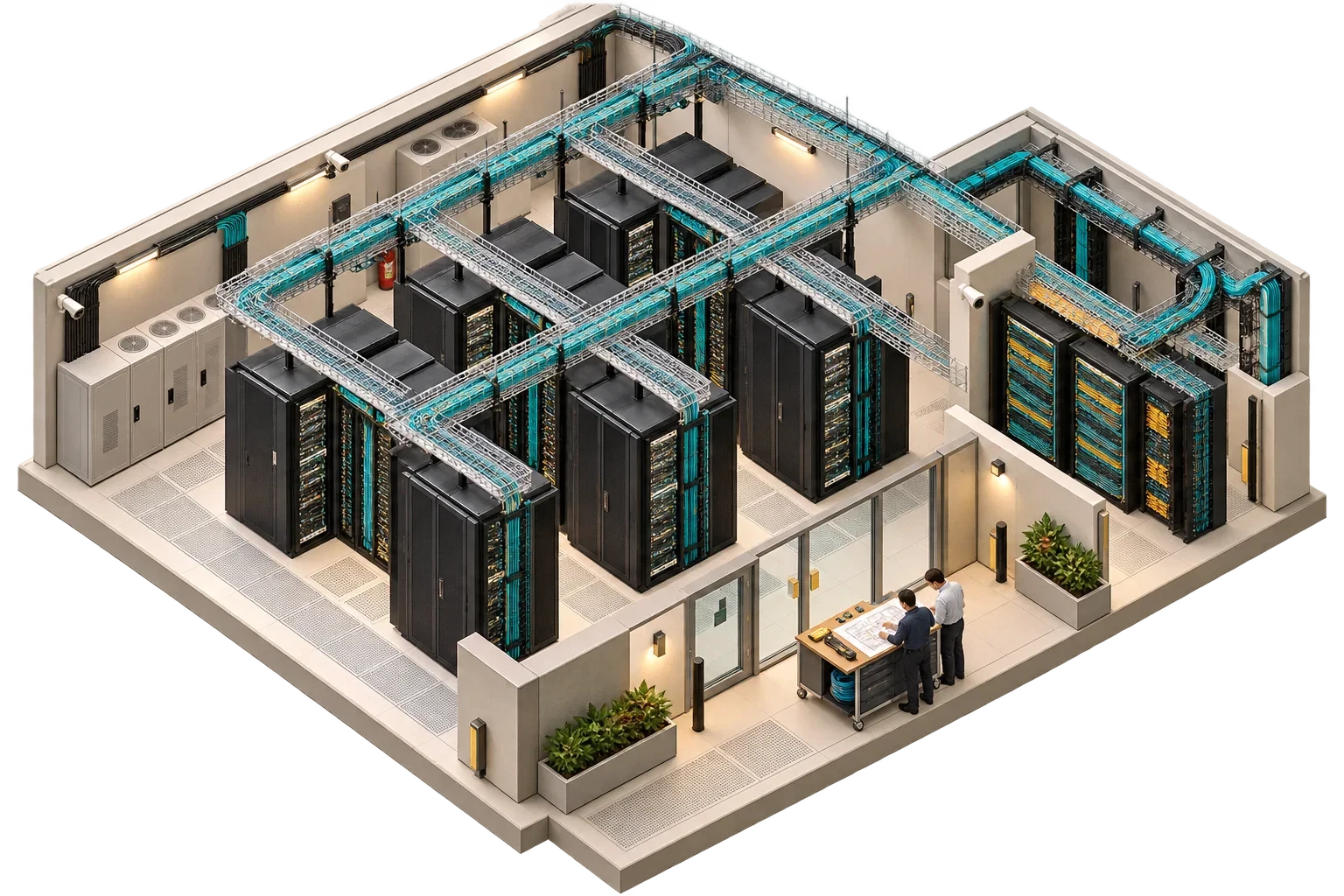
A common way to get data centre cabling wrong is to start with the cable: pick a category or a fibre type and work backwards. That leaves the important questions unanswered.
Structured cabling is the permanent, organised cabling between equipment cabinets, distribution points and external connections, installed to a standard and documented so that connections can be added and changed by patching, without pulling new cable. In a data centre it should be designed from the network architecture outwards: first which devices connect to which, at what speeds and over what distances; then the topology of distribution points; and only then the physical pathways.
Two families of standards are commonly used. ANSI/TIA-942, now in revision C, covers the telecommunications infrastructure of data centres and computer rooms, as well as site, architectural, electrical, mechanical, fire safety and security aspects. In the international ISO/IEC 11801 series, ISO/IEC 11801-5 specifies generic cabling within and to the computer-room spaces of data centres, while office and industrial spaces in the same premises fall under Parts 2 and 3. The designer should state which standard the design follows, because mixing them without saying so creates ambiguity at testing and acceptance.
The design begins with a list of the networks the facility will carry: the production data network, storage, out-of-band management, any high-performance compute fabric, building and security systems, and carrier connections. For each, it records port counts, speeds and the interface types the equipment supports.
Equipment distance limits come next, and high-performance fabrics impose constraints that ordinary enterprise networking does not. GPU cluster designs, for example, can set a maximum total cable path for every fabric link, and the vendor's documentation for the exact system is the place to find it. If a power limit then forces racks to be spread across more floor space, cable lengths must be recalculated and latency may be affected. Cabling, power and layout are a single design problem.
With the networks and limits known, the topology can be drawn: where the main and zone distribution points sit, how cabinets connect to them and how carriers enter the building, with room left for the networks that are known to grow. The pathways follow, whether overhead trays or under-floor routes, with separation between power and data, fire-stopping and physical diversity where resilience matters.
The pathways must also be coordinated with cooling. The US Department of Energy's data centre design guide warns that cable congestion in raised-floor plenums can sharply reduce airflow and promote hot spots. It recommends a cable management strategy for the whole air path, a programme to remove abandoned cables, and sealing of cable openings in floors and ceilings.
Last comes the information that keeps the installation usable: consistent identifiers for cabinets, panels, ports and links, a test regime for every installed link against the chosen standard, and a process that keeps the records current after moves and changes.
Spare capacity should follow a growth scenario, not a blanket percentage. What is the next stage of the network likely to be? Which pathways and panels would it use, and could it be installed without disturbing live services? Reserving tray space and panel positions is usually cheaper than reserving cables that may be the wrong type by the time they are needed.
Cabling sits between several disciplines, and gaps open up wherever each assumes another has made the decision.
| Decision | Usually led by | Must be coordinated with |
|---|---|---|
| Networks, port counts, speeds, interface types | Owner's IT team or network designer | Cabling designer |
| Distribution points, link design, test regime | Cabling designer | Network designer, operator |
| Containment routes, separation from power, loading | Cabling designer and electrical engineer | Mechanical engineer (air paths), structural engineer where loads are significant |
| Penetrations and fire-stopping | Architect and fire engineer, per the fire strategy | Cabling installer |
| Labelling and records format | Operator | Cabling designer, DCIM administrator |
Acceptance is where the earlier decisions are proved. Every link should have test results against the specified standard and performance class, and the labels at both ends should match the records. Installed routes, including the diverse ones, should match the drawings, and penetrations should be properly fire-stopped and sealed. The as-built records should arrive in a form the operator will actually maintain, ideally linked to the DCIM inventory.
For a new technical space or a dense compute expansion, the most useful drawing costs almost nothing: the second stage, sketched onto the first-stage layout while the cable is still unordered. A line is far cheaper to move on that drawing than a switch is in a live row.
This article connects to our work on Our services.
We can discuss how this subject fits the project brief.
Contact Pagin Consulting